Pull Cord Emergency Switches

These products are used to increase safety in the machine and conveyor line. In the plant, the system stops when the staff pulls the rope around the machine or at any point in a conveyor.These products are also called Pull Cord Emergency Switch, Pull Cord Switch.

Emergency Stop Switch

Pull cord emergency stop switches are used to ensure safety, both for personnel and to protect conveyor belts and all surrounding equipment. Regardless of the length or width of the conveyor belt system, it requires an emergency stop switch. Any mechanical failure or belt misalignment further increases the necessity of an emergency stop switch on conveyor systems.
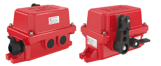
The pull cord emergency stop switch is also known as a rope pull emergency stop switch. Inside the device is a rope system that, when pulled, activates the stop function. This is essential in case of potential damage, as it protects the system, personnel, and the entire facility. Conveyor belt emergency stop switches help prevent widespread damages and losses both materially and morally.

There are four types of rope pull emergency stop switches, differing mainly in their internal structures. Particularly, the contact configuration may vary. While the standard contact structure is 1NO+1NC, it can go up to 3NO+3NC. Rope pull safety switches made of stainless steel or aluminum housing are produced with the highest quality materials. Especially due to the nature of the areas and facilities in which they are used, non-corrosive emergency stop switches come in different models. All rope pull emergency stop switches are resistant to weight and impact.

Each product complies with different standards. Some are CE and EAC certified, while others are designed to meet the installation requirements of USA-based facilities. Wire rope emergency stop switches that conform to these standards are also preferred. Standards in the rope system are crucial and may vary depending on the machine or conveyor system they are connected to.

Safety rope switches are categorized into two main groups: those operated manually and those operated remotely. In pull cord emergency stop switches, the rope is pulled to trigger the stop and reset the system. This provides the best safety measure against explosions and many mechanical problems. For installation, using KBT connection accessories will simplify the setup and ensure maximum stability.

Pull Cord Emergency Stop Switches — Technical Guide

01

Pull Cord Emergency Stop Switch: Operating Principle and Industry Terminology

A pull cord emergency stop switch allows personnel to stop a conveyor or long machine line from accessible points along the route. When the rope is pulled, the contact changes state and supports an emergency shutdown command. KBT offers composite and aluminium housings, several rope distances, contact arrangements and ATEX versions. Model selection should be based on line length, pull direction, environmental conditions and the safety circuit design.

Correct rope tension, support spacing and manual reset behaviour are essential for reliable operation. The selected model’s data sheet must be checked for maximum rope distance, contact configuration and environmental ratings.

Technical specifications and procurement documents commonly use “pull cord emergency stop switch”, “rope pull switch”, “pull wire emergency switch”, “conveyor emergency stop switch” and “pull cord switch”. Depending on the region and the monitored function, “emergency pull cord switch”, “pull wire switch”, “pull rope switch” and “safety pull cord switch” may also appear. These expressions overlap, but they do not make two devices interchangeable without checking actuator geometry, contacts, environmental limits and certification.

Relevant KBT product families on this category page include TPR22-PR, NSR22-PR, NSR66-PR and NSR90-PR. The model code identifies a product family; the exact actuator, contact arrangement, enclosure and certification must be confirmed from the selected version.

02

How to Select the Right Pull Cord Emergency Stop Switch

Selection must start with actual site data rather than a model name. Record Single- or double-sided rope connection and total line length, Composite or aluminium housing, IP rating, dust, moisture, temperature and impact, NO/NC or SPDT contact requirement and ATEX suitability for classified hazardous areas. Compare the shortlist with the current data sheet, dimensional drawing, certificate and control architecture; do not infer an unknown rating from a similar enclosure.

  • Single- or double-sided rope connection and total line length
  • Composite or aluminium housing
  • IP rating, dust, moisture, temperature and impact
  • NO/NC or SPDT contact requirement
  • ATEX suitability for classified hazardous areas

Exact limits, contact ratings and certification markings must be verified in the current product data sheet before ordering or commissioning. This verification applies specifically to the selected pull cord emergency stop switch configuration.

03

Installation and Commissioning

Mount the switch on a rigid support along the accessible side of the conveyor. Support the rope so that it does not rub machinery, form sharp bends or develop excessive sag, and account for thermal changes in rope tension. During commissioning, pull the rope at several points and verify the alarm, stop and manual-reset response through the actual control circuit.

Typical applications include mining, cement, steel, power, ports, recycling and bulk-material conveyor lines.

04

Contacts, Control Logic and Functional Validation

The pull cord emergency stop switch is a field device within a wider machine-control or safety function. Contact arrangement, PLC input, relay logic, alarm stage, stop stage and restart permission must be defined from the risk assessment. A contact change at the device is not sufficient proof: commissioning must confirm that the intended alarm or safe stop occurs at the machine.

Share the line length, pull direction and site conditions; we will help identify the appropriate switch and rope accessory combination.

05

Inspection and Preventive Maintenance

Inspect rope tension, fasteners, support eyes, enclosure and cable entries at planned intervals. Operate the mechanism in both directions and verify contact change and reset. Correct corrosion, impact damage, loose hardware or poor tension at its source rather than simply resetting the alarm.

06

Troubleshooting Guide

SymptomPossible causeRecommended check
Nuisance trip without a pullMounting geometry, contamination or operating conditions do not match the intended response of the pull cord emergency stop switch.Compare the installation with the dimensional drawing and reproduce the real operating movement under controlled conditions.
No trip from a remote pull pointThe actual process condition is outside the selected sensing range, travel or delay.Measure the operating point and compare it with single- or double-sided rope connection and total line length and the current model data sheet.
Manual reset cannot be completedMechanical wear, loosened fasteners, cable damage or an unsuitable electrical interface is affecting repeatability.Inspect the mechanism, mounting, cable entry, terminals and signal path separately; then repeat the functional test.
Rope is slack, broken or displacedThe original cause has not been removed, or commissioning settings and the real machine sequence no longer agree.Isolate energy, remove the process cause and validate the complete field-device-to-machine response before restart.
07

Frequently Asked Questions

How is a rope pull switch different from a mushroom emergency button?

A rope pull switch can be reached along a long route, while a mushroom button operates only at its installed location.

How is the rope distance selected?

Use the line layout, pull direction and the maximum distance stated in the model data sheet.

When is an ATEX version required?

Use a certified version when the installation point is classified for a potentially explosive atmosphere and the product marking matches that zone.

Which site data must be recorded before selecting the pull cord emergency stop switch?

Record Single- or double-sided rope connection and total line length, Composite or aluminium housing, IP rating, dust, moisture, temperature and impact, NO/NC or SPDT contact requirement and ATEX suitability for classified hazardous areas. These values determine whether the actuator, enclosure, contacts and operating range fit the real duty.

How is TPR22-PR commissioned on the actual machine?

Mount the switch on a rigid support along the accessible side of the conveyor. Support the rope so that it does not rub machinery, form sharp bends or develop excessive sag, and account for thermal changes in rope tension. During commissioning, pull the rope at several points and verify the alarm, stop and manual-reset response through the actual control circuit. The test record should show the measured operating point and the resulting PLC, relay, alarm or stop response.

What is the most common selection error for a pull cord emergency stop switch?

Choosing from the product name or enclosure alone. Single- or double-sided rope connection and total line length and Composite or aluminium housing must be checked together with the current drawing and data sheet.

How should the pull cord emergency stop switch be included in preventive maintenance?

Inspect rope tension, fasteners, support eyes, enclosure and cable entries at planned intervals. Operate the mechanism in both directions and verify contact change and reset. Correct corrosion, impact damage, loose hardware or poor tension at its source rather than simply resetting the alarm. The interval should be shortened when previous tests show drift, contamination, impact or accelerated wear.

Can the pull cord emergency stop switch be connected directly without checking the control logic?

No. For the pull cord emergency stop switch, contact duty, input type, alarm and stop stages, restart conditions and fault response must be engineered for the machine and verified during commissioning.

Which KBT families can be evaluated in this category?

The relevant KBT families are TPR22-PR, NSR22-PR, NSR66-PR and NSR90-PR. Suffixes and options can change the actuator, contacts, enclosure or certification, so the complete code must be verified.

What should be documented after a functional test?

For the pull cord emergency stop switch, record the model and full code, location, test condition, measured response, downstream machine action, result, date and responsible person.